2.6 NETWORKING TECHNIQUES IN RAILNET
2.6.1 Introduction
This is going to be a long and booooring topic. So, keep your popcorns and cold water ready in case you feel sleepy. OK let's continue HURAY!!!!
2.6.2 OSI (Open System Interconnect) Layers

 |
| OSI MODEL |
The Open Systems Interconnection model (OSI) is a conceptual model that characterizes and standardizes the internal functions of a communication system by partitioning it into abstraction layers. The model is a product of the Open Systems Interconnection project at the International Organization for Standardization (ISO), maintained by the identification ISO/IEC 7498-1.
The model groups communication functions into seven logical layers. A layer serves the layer above it and is served by the layer below it. For example, a layer that provides error-free communications across a network provides the path needed by applications above it, while it calls the next lower layer to send and receive packets that make up the contents of that path. Two instances at one layer are connected by a horizontal connection on that layer.
O S I Layers
1) Application Layer: Enables the user to access the network.
ex: File transfer, email, www
2) Presentation Layer: Converts the data to and fro between different standards and formats so that any type of PC can communicate with any other type. Compression, decompression, encryption and decryption takes place here.
3) Session Layer: Responsible for establishing, maintaining and terminating the communication between two PCs.
4) Transport Layer: Responsible for host to host message delivery. It fragments the data into packets and rearranges as per the sequence No. of the packets.
5) Network Layer: Routes the packets logically as per the logical addresses of the source & destinations. Interprets physical address (MAC address) from the logical address (IP address).
6) Data Link Layer: It addresses the packets, that is headers and trailers are added to a packet. At receiving end the headers/trailers are removed and the original message is retrieved. Flow control, media access and synchronization are done here. This layer is responsible for error control mechanism.
7) Physical Layer: Actual data transmission takes place here in the form of electrical signals. Signal encoding, decoding, type and mode of transmission, multiplexing techniques and interfacing are handled at this layer.
 |
| DATA TRANSMISSION PATH |
2.6.3 Data Transmission Techniques
- Store & Forward method of transmission.
- Each node stores the incoming packets.
- Every node sends the packets on the basis of 'First In First Out'.
- A node decides logically the shortest and efficient route to send data packets.
- All the nodes exchange with each other continuously the information pertaining to communication lines, congestion of the traffic etc called 'Routing Table'.
2.6.4 Network Topologies
Nodes in a network can be arranged in different manners calle the topology of the network. Every topology has its own advantages and disadvantages and are used according to cost and need of a network.
Types of topologies
- Bus Topology
All the nodes are connected to a common bus. Requires minimum of wiring
- Mesh Topology
Every node is connected to every other node. Uses Point to point protocol (PPP). Requires maximum wiring lengths.
- Ring Topology
Every node is connected to its adjacent node. The last node is connected to the first one. Uses Token Ring protocol. If any node fails the entire network goes down.
- Star Topology
- Every node is connected to a central Hub/Switch. Easy to implement and expand.
- Most widely used.
- If Hub/Switch fails entire network goes down.
- Tree Topology
- Extension of Star network.
- Every node is connected one of the Switches.
- These switches are in turn connected to one common Central Switch.
- This is the practical network topology in the field.
- If one of the switch fails also the remaining nodes will be in operation.
- Hybrid Topology
The hybrid topology is the combination of the basic topologies.
2.6.5 Packets and types of switching
Packets
- Information is split into small data chunks called 'Packets'.
- Headers containing address of source/destination and sequence No. are added to Packets.
Types of switching
 |
| FLOWCHART ON TYPES OF SWITCHING |
a) Circuit Switching
- A physical communication path is established between source and destination.
- This channel can not be shared by other nodes.
- Inefficient for data transmission.
b) Packet Switching
- Message is split into small data chunks of equal length.
- These are called 'Packets'.
- Headers are added to packets.
- Headers contains source/destination address and sequence No.
- Packets are transmitted over an available free route by the intermediate node.
1) Datagram Method
- All the packets may not be transmitted on the same route to the destination.
- Packets may not arrive in sequence at the destination.
- Receiver has to assemble the packets as per the sequence No.
1) Virtual Circuit Method
- A path is chosen between source and destination.
- A unique No. is given to this path called Virtual Circuit No..
- Entire message travels in the same path. Packets contains only the VC as header.
- Intermediate nodes simply read the VC No. and forwards to next node.
c) Message Switching
- Message is sent at once.
- Intermediate node stores the message and then forwards.
 |
| MESSAGE SWITCHING |
d) Frame Relay Switching
- Several packets are combined into one unit called 'Frame' of fixed size. (This frame size depends on the network path).
- Frames are transmitted on the network like packets.
- Information throughput is high.
e) ATM (Asynchronous Transfer Mode)
- Cell Switching An ATM Cell contains Header (5 bytes)+ Data (48 bytes) a total of 53 bytes (424 bits).
2.6.6 Types of network
1) LAN
- Local Area Network Nodes are connected within a small area like an office complex.
- The 100 mts permissible transmission length of the cable is sufficient.
2) MAN

a) Bridge
- Connects two similar networks.
- Reduces traffic by routing packets logically.
- Data packets Originating from Network 'A' and addressed to one of the node in Network 'A' are routed to Network 'A'.
- Data packets Originating from Network 'A' and addressed to one of the node in Network 'B' are routed to Network 'B'.
- This reduces traffic on the inside Router.
b) Hub( Explained earlier )
c) Gateway
- Used to connect Networks with different protocols/architecture.
- Converts the protocol/formats of the messages as per the connected Networks protocol/formats.
- ex: Converts the data packets with ASCII coding to EBCDIC coding and delivers to the destination Network.
d) NIC card ( explained earlier )
 |
| NIC |
e) Repeater
- Acts like Signal Boosters.
- Regenerates the incoming pulse streams.
- Detects the incoming digital signals which are weak in amplitude.
- Regenerates the corresponding digital signals afresh with required levels of amplitude.
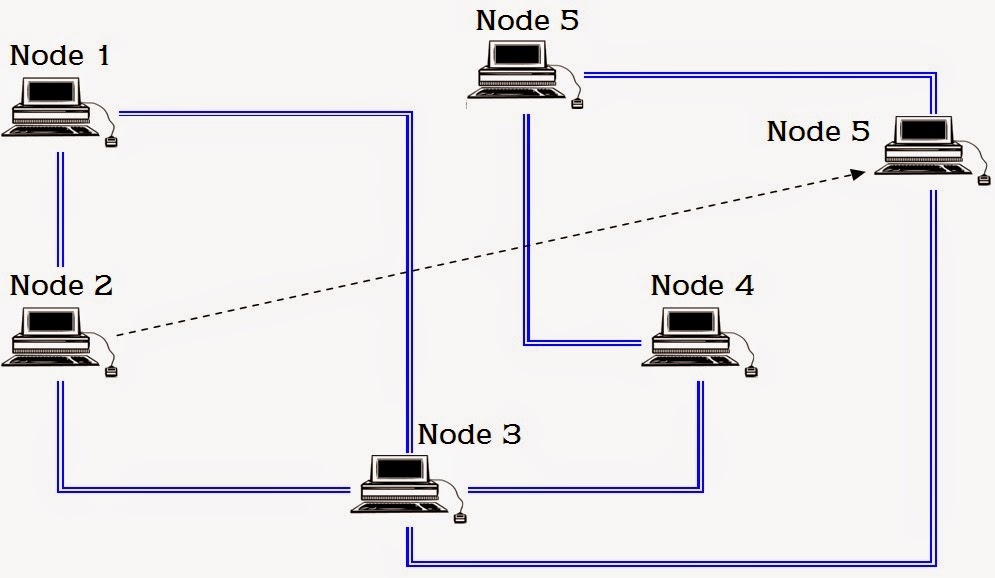
f) Router
- Directs data packets to specific Network as per the address.
- Joins different types of Networks.
- Offers security for the user information.
- Logically decides the efficient route for the data.
- Routing Table is maintained.
- Routing Table contains the adjacent Router's Information regarding communication path status, congestion, quality of the transmission line etc.
- Every second, Routing Tables are exchanged between connected Routers.
- Uses logic to forward the data packets called 'Routing Algorithm'.
- Router is a more sophisticated device than a hub/switch.
- It determines the best network path to send the packets.
- It maintains an up-to-date network topology in memory called Routing Table.
- Routers exchange their Routing Tables periodically with each other on the network.
- Bridging is faster than Routing Router divides a LAN into small networks.
- Router offers security and controls broadcasting of packets.
 |
| ROUTER IN A NETWORK |
 |
| ROUTER CHOOSING PATHS |
g) Switch ( explained earlier )
2.6.8 Intranet
2.6.8 Intranet
- Internal Network.
- Owned by an organization.
- ex: IRISET, LIC, SBH
- Makes use of security through firewalls.
- Traffic from Internet is restricted at access point.
2.6.9 Internet
- Collection of Networks.
- Network of Networks.
- Heterogeneous of Networks connected into a broader Network.
- www is one of the application of Internet.
- Email and file transfer protocols are most widely utilized by the users on Internet.
2.6.9 TCP/IP


- Transmission Control Protocol/Internet Protocol.
- Widely used protocol on Internet.
- Practically any computer can communicate with any other computer on the globe with this protocol.
TCP/IP Protocols
- Telnet - Remote Login.
- FTP - File Transfer Protocol.
- TFTP - Trivial File Transfer Protocol.
- SMTP - Simple Mail Transfer Protocol .
- POP - Post Office Protocol .
- IMAP - Internet Message Access Protocol.
- MIME - Multipurpose Internet Mail Extension.
- SNMP - Simple Network Management Protocol.
2.6.9 IP addressing ( logical addressing)
- Every computer connected to the network should be assigned with an IP Address for identification purpose. (ID) .
- IP address takes the form ' A.B.C.D. ' Each block is denoted by eight bits.
- Each block of address may takes the value from 000 to 255 ex: Binary: 10011010 . 00000011 . 01101101 . 00011011 Decimal: 201.202.10.156 .
- Basing on IP address only a node is recognized on a Network.
- Present IP address is of version four. Four groups of eight bits each, 32 bits length.
- 2 raised to the power 32 Addresses can be implemented in this version.
- Some Addresses are not allowed on the Internet.
- Future IP address is of version six.
- Eight groups of sixteen bits each, 128 bits length.
- IP Addresses are allotted by ICANN (Internet Corporation for Assigned Names & Numbers)
- IP Address is divided into Net ID & Host ID.
- ex: 201.202.10.156 This is a class C IP address (Net ID=first three bytes) 201.202.10 is the Net ID, 156 is the Host ID.
No comments:
Post a Comment